
ARTEC Info: 4G63 Exhaust Manifold - Talking Flow
Recently we've seen some questions come up around our 4G63 Stock Frame / Direct Replacement exhaust manifolds, specifically surrounding port and gasket matching on both the exhaust and turbo side.
We have decided to publish the following information in order to answer any questions and clear up any confusion. This article will be focused specifically on our 4G63 Stock Frame / Direct Replacement Exhaust Manifold.
Firstly, there is some basic information that must be outlined and understood before we can make assumptions about products and effects of air flow.
Head Flow
Existing data from multiple threads and posts (see data from AMS Performance) has shown that a factory stock Evo 8/9 4G63 head flows approximately 205 CFM @ 28” of vacuum at .350”-.380” of valve lift on the exhaust side.
The stock 4G63 exhaust cams have .374 or 9.5mm of lift.
It is important to note that 205 CFM is the peak flow number, and not the average of flow throughout the whole valve sweep. The average flow is far lower.
The CFM flow of a 33mm ID runner is 206 CFM @ 28”of vacuum as measured on our in house 1200 CFM digital flow bench.


Port Sizes
The factory exhaust port size on an Evo 8/9 4G63 is 50.45mm X 31.72mm.


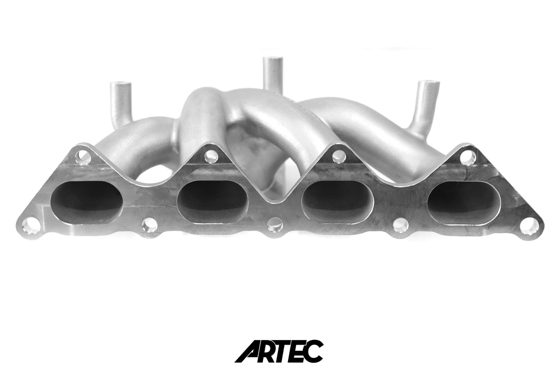
The ARTEC 4G63 Stock Frame / Direct Replacement Exhaust Manifold exhaust port size 52.5mm X 32.7mm.
An OEM Mitsubishi exhaust gasket measures up to 57.73mm X 40.8mm.
For completeness, we have also measured a ported 4G63 head at 50.91mm (yes you can go wider) x 32.64mm (yes you can go taller).
Here is a chart summarising the sizes:
| Stock Exhaust Port | Oversized Port | ARTEC Exhaust Port | OEM Gasket | |
| Width | 50.45mm | 50.91mm | 52.5mm | 57.73mm |
| Height | 31.7mm | 32.64mm | 32.7mm | 40.8mm |


As we can see, the ports on the ARTEC exhaust manifold flange are slightly larger than the port size on the factory head, and also the slightly oversized head. There is no need to port out to the gasket when using a factory head and the ARTEC manifold. The gasket is there to seal the components and flow!
Head Flow vs Runner Flow
Let’s go back and talk about the flow of the runner vs the flow of the head.
When tested, a head is flowed with NOTHING attached to it. So, this is the absolute maximum it can and will flow.
As mentioned above, we know a 33mm ID runner will ALSO flow the same as the head in perfect conditions (both at 205-206 CFM). If you make a runner larger and flow 350 CFM, it won’t make an exhaust port flow a greater amount than what it does under ideal conditions. What it will do is increase the internal volume of the manifold. Something that you DO NOT want.
This is also shown and supported by most OEM’s today that design and develop very small to no exhaust manifolds on their modern turbo charged performance cars. The larger the volume of the exhaust manifold, the larger the decrease in response. Please don’t reference long runner large diameter F1 cars or other purpose-built race cars that do not operate below 7500 RPM with their turbo designs.
Turbine Housing Design
Ok, let’s now look at the OEM turbine housing design and its key sizes.
The split pulse housing has 2 ports which total 3034 square mm. For reference a split pulse T4 has a cross sectional area of 3200 square mm.
If you are aware of how much flow can be had with a T4 split pulse housing you will know that 1300hp + is not an issue with back pressure, as its more to do with the scroll and turbine wheel designs.
If you look at the OEM design of the manifold and the turbine housings, you will find there is a factory step from the slightly smaller turbine flange size to that on the turbine housing itself. This would be for speed of production in the manufacturing process, and to not cause any flow issues if there is a slight misalignment during installation.

So, the factory turbine flange is approximately 2 mm larger, all the way around the outside profile, than the manifold, which is the same for the ARTEC unit.
Why? Because with the first 4-10mm of the turbine housing it’s already at the same profile size or smaller, thus not causing any flow issues.

If you have ever looked inside the turbine housing entry you will notice the wastegate port and the surrounding area are designed to try and promote flow to the valve to allow it to function correctly. What you will also notice is that after the wastegate (the beginning on the turbine scrolls) it is VERY small. As you can see from the photos and our measurements you will see that the entry size has nothing to do with the turbine A/R, nor is it limiting the peak flow in any way.

We have carefully reproduced the entry profile of the turbine so it’s easy to see the actual size of the beginning of the scroll. From this point onwards it reduces in size.
Please review the attached images so you can see for yourself at how the cross-sectional areas compare.


We have also included photos of the male plugs taken from the turbine entry as well as the entry to the manifold from the head.


We hope this information has answered many questions and cleared up any confusion surrounding head flow and exhaust manifold flow.